Real robot find wall issue

Hello World,

I am facing an issue with the “ROS2 Basics in 5 Days (Python)” project. Specifically, the problem occurs in the second part, “Find Wall.” In this section, we are tasked with writing a service server. When this service is called, it should orient the robot to its right side to initiate the wall-following behavior. While the code works Perfectly in the simulation, it encounters issues in the real-world lab setting.

Firstly, my logic for finding the wall is as follows: The robot rotates until it identifies the closest wall or until the laser_min_index reaches 360 degrees. Then, it moves forward until the distance to the wall is less than 0.3 meters. At this point, the robot stops and rotates until the laser_min_index becomes 270, ensuring that the robot’s right side is aligned with the wall. This logic works perfectly in the simulation.

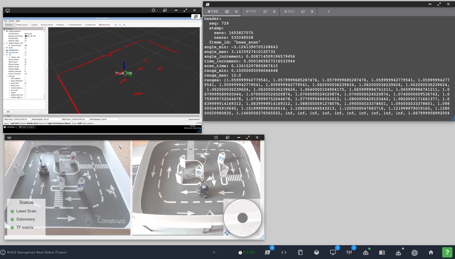
However, in the real robot lab, I’m facing several issues. First, the laser scan range is not 360 degrees; it is actually 719 degrees. Second, as the robot moves toward the wall, the distance reading from the laser actually increases instead of decreases. This leads to the robot getting too close to the wall and eventually crashing into it. Lastly, I’m encountering numerous problems related to the sensor readings.

I hope someone can understand the issues I’m facing and offer some guidance. Feel free to ask for more information.

Thank you.

Please anyone can help :slightly_smiling_face:

Hi @ghassan11 ,

You are not facing “issues” with the real robot. It is the configuration on the real robot.

The laser scanner ranges are 360 values. It is not 360 degrees. The real robot has 720 values instead of 360 values. To be clear, the simulation robot has 360 range values for 360 degrees, the real robot has 720 values for 360 degrees.

This is obvious given the fact that you have programmed the robot based on the 360 range values scanner model. So when you run the program on a 720 scan ranges model, the “front laser scan range” does not coincide with the actual front range on the real robot, therefore the robot goes and crashes straight into the wall.

Which sensor readings? Please explain.
You do not need any other sensors other than laser scanner and odometry.
Although you have IMU and TFs, those are not really required. You can use them if you want to. But using these topics are not really the scope of this rosject.

I will give you a hint (not a solution). Because I want you to think and come up with a way to solve this situation yourself - because you are learning robotics.
Hint: Set a variable for scan ranges that can be set to either 360 or 720. So when you are using the simulation you can use 360 and for the real robot you can rebuild the project with 720. Then set all the references to the sides based on a multiple of the scan ranges value.
This is the easiest fix for your problem.

Regards,
Girish

1 Like

Hi Ghassan,
if you connect to the robot and get the info of a LaserScan of the robot on the topic /scan you will get the following:

user:~$ rostopic echo -n1 /scan
header:  seq: 729  stamp:
    secs: 1693827075
    nsecs: 535048558
  frame_id: "base_scan"
angle_min: -3.1241390705108643
angle_max: 3.1415927410125732
angle_increment: 0.008714509196579456
time_increment: 0.0001865827216533944
scan_time: 0.13415297865867615
range_min: 0.15000000596046448
range_max: 12.0
ranges: [1.059999942779541, 1.0579999685287476, 1.0579999685287476, 1.059999942779541, 1.059999942779541, 1.059999942779541, 1.059999942779541,...

This indicates that the lidar in the T3 real robot measures only from -90º (angle_min) to 90º (angle_max), in angle increments of 0.5º (angle_increment).

This means, the ranges array will contain 180 / 0.5 = 360 laser rays.

If the lidar starts measuring from -90º (that is, ray 0 in the array), the center of the robot will be the ray 179. That is the ray that has to have the min value, when the robot rotates to find the wall.

Once the robot has approached the wall and starts rotating to be aligned to the wall, the ray that has to have the minimum distance value is the ray number 0 (that means, the -90º) so the robot is right aligned to the wall.

For the simulation, the data of the scan is different. This is made on purpose to practice with this type of changes between simulations and real robots. Never a simulation is the same as the real and you must know how to check that.

So if we check the /scan topic of the simulation, we obtain the following:

header:
  stamp:
    sec: 40
    nanosec: 621000000
  frame_id: base_scan
angle_min: 0.0
angle_max: 6.28000020980835
angle_increment: 0.01749303564429283
time_increment: 0.0
scan_time: 0.0
range_min: 0.11999999731779099
range_max: 3.5
ranges:
- 1.1701221466064453
- 1.1733304262161255
- ...

So in this case, the robot lidar is measuring from 0º to 360º (that is a full round). Then ray number 0 would be the ray that is in front of the robot. Also, the lidar has a ray every 1º (angle_increment) so in total has 360 rays (same number as in real but organized in a different way).
This means, when the robot is approaching the wall, the minimum distance should be on ray 0, but when the robot is aligning to the wall (to the right), the minimum distance must be at ray 270.

I hope this clarifies how to attack the project. We are also going to clarify all this in the project itself for new students.

Additionally, to our understanding, the sensors of the real robot are measuring properly, as you can see in this image

Please clarify what you mean by wrong readings

Keep pushing your ROS learning!

2 Likes

Thanks Soo much Sir :heart_eyes:

This is what I wanted because the lidar readings is not the same in the simulation and in real robot thanks for clarifying .

Please can you help me in some thing as I know that the front laser readings in simulation can be 0 or 359 but in real it can be only 359 ?

Second thing can you tell me if it is correct , if I want my robot to go to the nearest wall it should rotates until the min_range_index becomes 359 then it goes towards the wall then it should keeps the robot right side to the wall so in the simulation the right is 270 but in the real robot is 180 please correct me :smiley:

So now I think my increasing issue of the value when it goes towards the wall is that I but the front reading in 0 which works in simulation but not in real because in real the back reading is 0 and 719 so the robot when it moves towards in real it is going more away :sweat_smile: please correct me if I am wrong :smiley: thank Sir for helping i got you

As you said it will be very good for the students if you noticed them that the readings is not the same because I am struggled in this more than 3 weeks :sweat_smile: I think because my age I am still 15 but age is just a number :wink: :saluting_face:

Best Regards
Ghassan

Sorry it was misunderstand it is not Wrong Readings it is Different Readings :sweat_smile: Thanks for clarifying

Please sir can you tell me what is different between simulation and Real robot and also sorry i did not get you what you mean by :

f the lidar starts measuring from -90º (that is, ray 0 in the array), the center of the robot will be the ray 179. That is the ray that has to have the min value, when the robot rotates to find the wall.

Once the robot has approached the wall and starts rotating to be aligned to the wall, the ray that has to have the minimum distance value is the ray number 0 (that means, the -90º) so the robot is right aligned to the wall.

i did not git you :sweat_smile:

In the following figure you can see the basic frames of the Turtlebot 3 real robot:

  • The red pole is the x axis, the green pole is the y axis and the blue pole is the z axis.
  • The robot front is oriented towards the x axis. This means, the robot is looking in the direction of the x axis.
  • The orientation angle of the robot is measured relative to the x axis.
    • So, an angle of 0 degrees means the front.
    • An angle of 90 degrees means the same direction as the y axis (to the left of the x axis)
    • An angle of -90 degrees means the same direction as the -y axis (to the left of the y axis)

So, when the laser says it is measuring from -90 degrees it means that the first reading in the ranges array of the LaserScan (the reading number 0) corresponds to a distance measured in the direction of the -y axis.

A measurement of distance to the front of the robot, means an angle of 0 degrees. That angle, in the specific LaserScan of the real Turtlebot means the ranges value of position 179. The same measurement in the simulated robot would mean the ranges position number 0, because the simulator lidar starts measuring at 0 degrees.

Hope this helps

Please can you help me in some thing as I know that the front laser readings in simulation can be 0 or 359 but in real it can be only 359 ?

Second thing can you tell me if it is correct , if I want my robot to go to the nearest wall it should rotates until the min_range_index becomes 359 then it goes towards the wall then it should keeps the robot right side to the wall so in the simulation the right is 270 but in the real robot is 180 please correct me :smiley:

So now I think my increasing issue of the value when it goes towards the wall is that I but the front reading in 0 which works in simulation but not in real because in real the back reading is 0 and 719 so the robot when it moves towards in real it is going more away :sweat_smile: please correct me if I am wrong :smiley: thank Sir for helping i got you

This topic was automatically closed 5 days after the last reply. New replies are no longer allowed.