I am building the URDF for the FastBot robot and I am stuck on two things related to the base plate geometry and wheel axle positioning. Would appreciate some help!
Background:
The FastBot has a two-part base plate:
Larger plate (front, houses caster wheel): 78mm in X, 120mm in Y, 3mm thick
Smaller plate (rear, houses drive wheels): 72mm in X, 92mm in Y, 3mm thick
I am using the convention: X=forward, Y=left, Z=up.
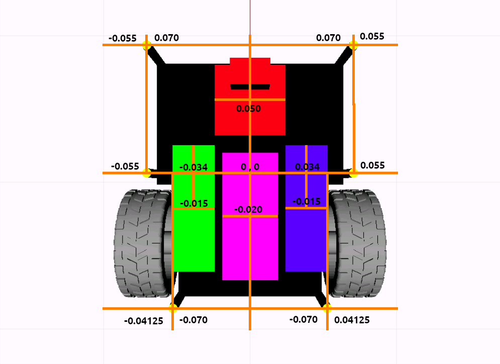
Question 1: What do the ±0.070 markings represent in the top view?
In the reference CAD top view image, there are orange bounding box annotations showing ±0.070 in the X direction. However:
The larger plate is 78mm in X
The smaller plate is 72mm in X
Combined length = 150mm
None of these cleanly explain where ±0.070 comes from. My best guess is that the origin (0,0) is not at the junction of the two plates, and ±0.070 represents the front and rear ends of the combined plate — but that would make total length 140mm which doesn’t match 150mm either.
Is there an overlap between the two plates that I am missing?
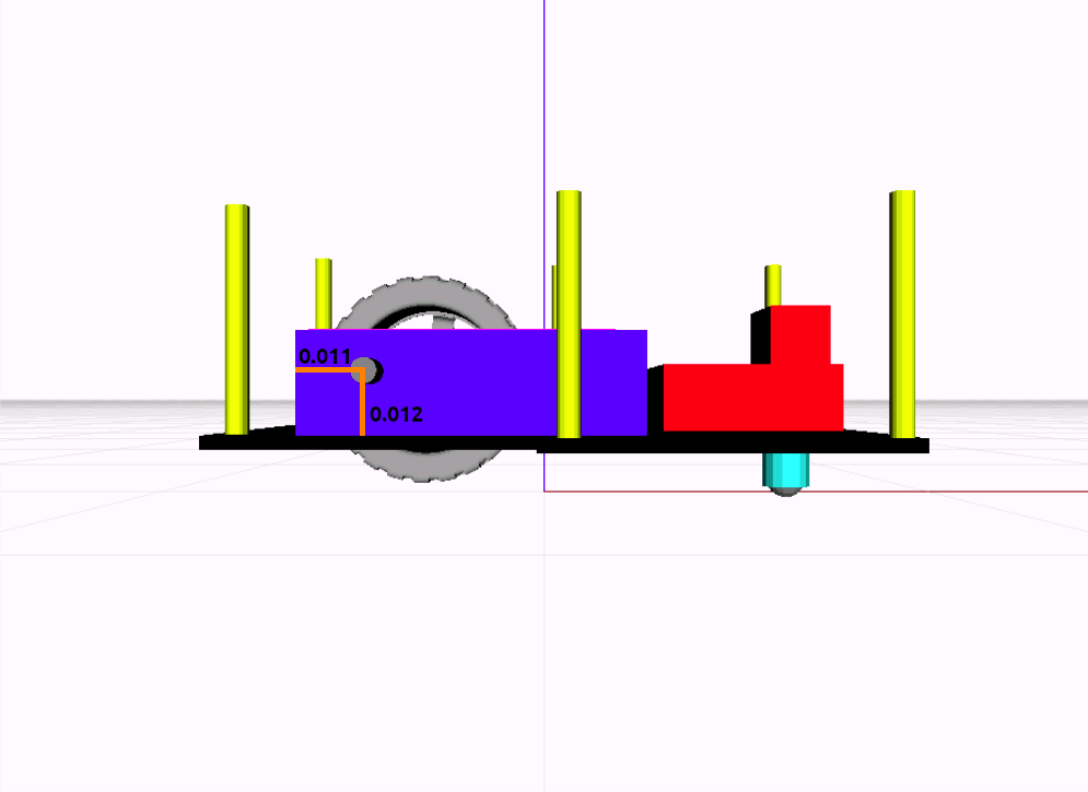
From the side view image, the motor shaft annotation shows the axle is 0.011m from the rear end of the motor+support block. The motor+support block is 75mm long in X, with its center at x = -0.015mfrom origin, giving:
Rear edge of motor block = -0.015 - 0.0375 = -0.0525m
Axle position = -0.0525 + 0.011 = -0.0415m
The drive wheels have a 32.5mm radius. Is x = -0.0415m the correct position for the wheel joint origin in the URDF.
Alternatively, do the STL files of the wheel already have the position offset we need for the wheel?
Any help or clarification would be greatly appreciated!
It is the distance from the center of the robot in the Y-axis of the image (in the up-down direction).
So the 0.070 denotes that the object is at 70 mm from the center on the direction up (positive X axis of the robot or positive Y axis of the image). Similarly the opposite is true for -0.070 value.
The values denote the distance from the center to the object it is referred close by.
For example, the value (-0.055 and 0.070) on the top left of the top-view image provides the distance from the center of the robot to the center of the yellow spacer.
Yes, the origin (0, 0) is not at the junction of the two base plate sizes of the robot. Yes, the robot design is quite weird, I am aware!, It is what it is!).
The two sections of the bottom plate do not overlap. It is a combination of two different size rectangles!
This calculation is correct!
NO. The stl files do not have the origin at the center of the wheel. It is located at some weird corner, hanging lose in mid-air.
So when you are positioning the wheel, just make sure you align the center of the wheel in the same axis as the center of the axle. Key point here is to go by visuals and not by numbers. Numbers get really confusing here!
I hope I have clarified your doubts sufficiently.
If you still have more questions or still confused, don’t hesitate to reply!