Cartographer Map not forming properly (ROS2 nav2)

Hi all,
I am working on my own URDF in ROS2 navigation using cartographer.

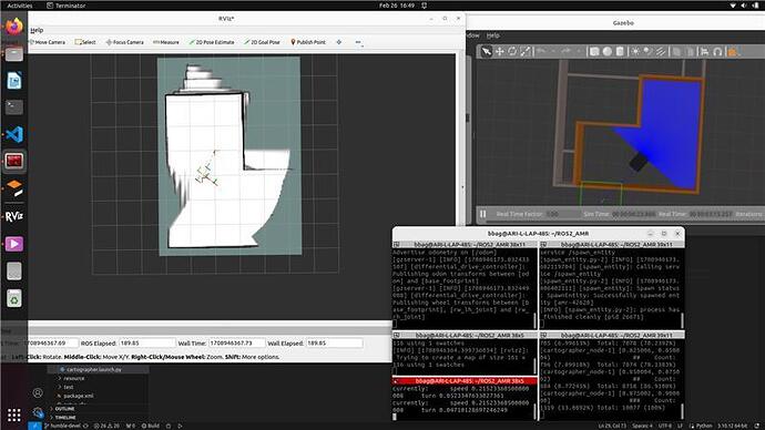
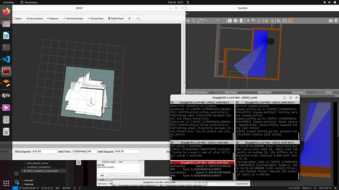
During mapping, parts of the maps tend to duplicate and sometimes form in an almost fidgeting way. i have tried changing the values in the “.lua” parameter file, update rates etc,but that did not resolve the issue.

When i decreased the speed it works as intended, but sometimes it doesn’t.

Attaching images.

Trial 1:

Trial 2:

Trial 3:


I tested the same using Turtlebot3 and it works great, attaching:

also attaching the parameter files:

include "map_builder.lua"
include "trajectory_builder.lua"
 
options = {
  map_builder = MAP_BUILDER,
  trajectory_builder = TRAJECTORY_BUILDER,
  map_frame = "map",
  tracking_frame = "base_footprint",
  -- tracking_frame = "base_link",
  published_frame = "odom",
  odom_frame = "odom",
  provide_odom_frame = false,
  publish_frame_projected_to_2d = true,
  use_odometry = true,
  -- use_nav_sat = false,
  use_nav_sat = true,
  -- use_landmarks = false,
  use_landmarks = true,
  num_laser_scans = 1,
  num_multi_echo_laser_scans = 0,
  num_subdivisions_per_laser_scan = 1,
  num_point_clouds = 0,
  -- lookup_transform_timeout_sec = 0.2,
  lookup_transform_timeout_sec = 0.02,
  -- submap_publish_period_sec = 0.3,
  submap_publish_period_sec = 0.03,
  pose_publish_period_sec = 5e-3,
  trajectory_publish_period_sec = 30e-3,
  rangefinder_sampling_ratio = 1.,
  odometry_sampling_ratio = 1.,
  fixed_frame_pose_sampling_ratio = 1.,
  imu_sampling_ratio = 1.,
  landmarks_sampling_ratio = 1.,
}
 
MAP_BUILDER.use_trajectory_builder_2d = true
 
-- TRAJECTORY_BUILDER_2D.min_range = 0.12
TRAJECTORY_BUILDER_2D.min_range = 0.05
-- TRAJECTORY_BUILDER_2D.max_range = 3.5
TRAJECTORY_BUILDER_2D.max_range = 5
TRAJECTORY_BUILDER_2D.missing_data_ray_length = 3.0
-- TRAJECTORY_BUILDER_2D.use_imu_data = false
TRAJECTORY_BUILDER_2D.use_imu_data = true
TRAJECTORY_BUILDER_2D.use_online_correlative_scan_matching = true
TRAJECTORY_BUILDER_2D.motion_filter.max_angle_radians = math.rad(0.1)
 
-- POSE_GRAPH.constraint_builder.min_score = 0.65
POSE_GRAPH.constraint_builder.min_score = 0.8
-- POSE_GRAPH.constraint_builder.global_localization_min_score = 0.7
POSE_GRAPH.constraint_builder.global_localization_min_score = 0.9
 
-- POSE_GRAPH.optimize_every_n_nodes = 0.2

I have been stuck on this a while, kindly support.

Hi @Joseph1001 ,

Are you working on a real robot or simulation? I am assuming it is simulation currently.

I think this is a problem with odometry. Initially I thought it might be something to do with map image pyramid formation (image processing stuff) but then I realized it can’t be that.

What is happening is that there is odometry drift and the robot is somehow also trying to correct its position while mapping. This is what causes multiple border effect resulting in dimensionally similar smaller map images.

So firstly I would check/debug the odometry. What devices / hardware components are you using for odometry? IMU, Wheel Encoders, GPS or any other form of navigation devices? Are they separate or fused together?

If they are separate, check the drifting. Try to use another device or fuse another sensor to perform better odometry.
If you are already using sensor-fused data for odometry, check what is the drift or error in odometry.

You can check your odometry in simple steps:
You need the following:

  1. Simulation setup properly.
  2. Position of Robot from Simulation (Gazebo).
  3. Sensor-fused estimate of Odometry.
  4. Odometry error (this is not a constant value).

How to check:

  1. Start simulation.
  2. Check linear-only odometry:
    1. Move robot in simulation linearly
    2. Get position and orientation of robot from Gazebo
    3. Simultaneously get the calculated odometry
    4. Get the values from odom frame
    5. Compare how close is the actual position of robot in Gazebo vs calculated odometry.
    6. If you have any linear or non-linear odometry drift, apply appropriate filter - PID, Kalman, Savitzky-Golay, LMS, RMS, Moving Average, whichever you like.
  3. Check angular-only odometry. Repeat step 2, but for angular movement this time.
  4. Once you have understood your error model, apply odometry filter.
  5. Use the odometry filtered values for Navigation.

You will always need sensor fused odometry provider because:

  1. Wheel encoders have additive drift errors and usually reports lesser values.
  2. IMUs have multiplicative drift errors and usually reports greater values.
    So you need to fuse them to get stabilized reliable odometry.

I hope this helps!

Regards,
Girish

1 Like

HI @girishkumar.kannan ,
Thank you for looking into this.

Let me try out the odometry drift and sensor fusion troubleshooting you mentioned.

This topic was automatically closed 5 days after the last reply. New replies are no longer allowed.